Safety Requirement Specification (SRS)

The Safety Requirement Specification (SRS) is a crucial document in the field of functional safety engineering. It is a comprehensive document that outlines the safety-related requirements for the system, product, or process.

The objective of SRS, as given in [IEC 61511-1, 10] is “to specify the requirement for the SIS, including any application programs and architecture of the SIS”.

The example of safety instrumented systems might include:

  • Shutdown systems for processes;
  • Fire and gas detection;
  • Railway Signalling;
  • Interlocks for dangerous machinery.

Hence, the primary purpose of the SRS is to ensure safety goals are clearly defined and the necessary measures are taken to achieve and maintain functional safety throughout the entire lifecycle of the system. The following are the key components of SRS.

1. System Overview – An introduction and high-level description of the system under consideration. This section provides context for the safety requirements and describes the purpose and functionality of the system.

  • Identify Regulatory requirements and project specifications
  • Identify the target SIL. (e.g. SIL-1, SIL-2, SIL-3)
  • Identify the possibility of Common Cause Failure (CCF) (e.g. HAZID, Human Errors)

2. Safety Goals and Objectives – Clearly defined safety goals and the objective that the system must achieve. Safety goals are often derived from the results of a systematic hazards and risk analysis.

  • Describe the objective of the safety function. (e.g. PHA, HAZOP, LOPA, FMEA)
    • To prevent tank overfilling by closing the inlet valve on a high liquid level;
    • To prevent vessel overpressure by opening the vent valve on a high pressure.
  • Describe all the SIF necessary to achieve (e.g., cause and effect diagram, logic narrative)

3. Functional Requirements – Details descriptions of the safety functions that the system must perform. This includes specifying the input conditions, expected behavior, and output conditions of each safety function.

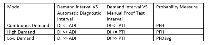
  • Identify the required SIL and mode of operation (e.g., Low demand/ Continuous)
  • Identify the Safe State where the safe state is defined as the state of the process when safety is achieved (e.g., Fail Open, Fail Close, Fail Last)
  • Identify the input condition (e.g. operating range, accuracy, trip set point, number of input, type of input, and architecture)
  • Identify the logic functions and required permissive, if any (e.g. logic diagram)
  • Describe the output actions and the criteria for successful operation. (e.g. number of output, type of output, architecture, and feedback)
  • Describe the failure mode for each SIF (e.g. alarm, automatic shutdown)
  • Identify the function requirement for the operation (e.g. manual shutdown, manual/semi-auto/automatic final element reset)
  • Identify the function requirement for preventive maintenance (e.g. by-pass)

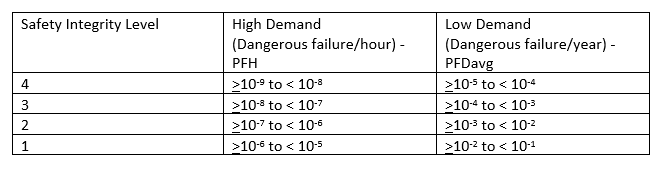
4. Performance Requirements – Quantitative or qualitative criteria that the system must meet to achieve the desired level of safety. This may include requirements related to Safety Integrity Level (SIL), availability, reliability, and other performance metrics.

  • Identify sources of demand and demand rate (e.g. SIL Classification, Historical accident frequency)
  • Identify the maximum allowable Spurious Trip Rate (STR);
  • Identify the requirement of Proof Test Interval (PTI);
  • Identify the achievement of the Probability of Failure average (PFDavg)
  • Identify the function Response Time (RT) to bring the process to a safe state within the process safety time (Detection time + Processing time + Actuation time + Feedback time)
  • Identify the Mean Repair Time (MRT)
  • Identify the time required for survival against MAE (e.g. 2 hr fireproof safe)

5. Interface Requirement – Specifications for the communication and interaction between system components, especially those relevant to safety functions. This ensures that the safety-critical information is exchanged accurately and reliably.

  • Identify all interfaces between SIS and the other system, if any (e.g. DCS, HMI, PLC, human)
  • Identify limitations and constraints of the hardware and embedded software.

6. Environmental and Operational Conditions – Description of environmental and operational conditions under which the system is expected to operate safely. This may include temperature ranges, humidity levels, and other environmental factors.

  • Identify the environmental condition (e.g. temperature, humidity, harsh marine environment, HAC, flooding, lightning)

7. Validation and Verification Requirement – Criteria and procedures for validating and verifying that the system meets the specified safety requirements. This involves testing, analysis, and other verification activities throughout the system development and operation.

  • Identify proof test procedure (e.g. frequency, work instruction, provision of temporary safety device that has to be provided during proof test interval, human aspects, consequence if the proof test goes wrong)
  • Identify procedures for shutdown, starting up, and restarting the SIS.

8. Documentation Standards – Guidelines for documenting and managing safety-related information throughout the lifecycle of the system. This ensures that the records are maintained and that changes to the system are properly documented.

9. Dependencies and Constraints – Identification of any dependencies or constraints that may impact the achievement of safe goals. This includes external factors that need to be considered in the system design and operation.

Oil Spill Hazards

Impacts

Environmental impact: Water Contamination, and Sediment Contamination.

Wildlife Impact: Direct harm to marine life, Toxicity, and Disruption of food chains.

Oil spills can have a range of adverse effects on the environment, ecosystems, wildlife, and human communities. The severity of these effects depends on factors such as the volume of oil spilled, the type of oil, the location of the spill, and the effectiveness of response efforts. Examples of impact such as;

Economy impact: Business disruption to the fisheries and Tourism industry

Human Health Impact: Air Quality (if oil burning), Contaminated Seafood, and Long-Term effects (chronic exposure).

Safeguard protection

Safeguard protection against oil spill hazards involves a combination of preventive measures, preparedness planning, and effective response strategies. Examples of safeguard protection against oil spill hazards such as;

Preventive Measure

  • Strict Regulatory Compliance: There are several international standards such as the International Maritime Organization (IMO) MARPOL Annex I and the International Convention and Oil Pollution Preparedness, Response and Co-operation (OPRC) which provides a framework for combating major incidents or threats of marine pollution.
    • Annex I Regulation for the Prevention of Pollution by Oil
      • Crude Oil Washing operations procedure;
      • Oil Record Book;
      • Shipboard Oil Pollution Emergency Plan, SOPEP
  • Vessel Maintenance: The American Bureau of Shipping (ABS), Lloyd’s Register (LR), and Det Norske Veritas Germanischer Lloyd (DNV GL) provide rules and guidelines for the design, construction, and maintenance of vessels.
  • Use of Double-Hulled Vessel: Implementation of double-hulled vessel designs, which provide an additional layer of protection against oil spills in the event of collision or grounding.

Oil Spill Response Planning

  • Contingency Planning: The main activities during developing the Contingency Plan such as To understand application regulation, Risk Assessment, Identify critical response elements, Identify communication plan, Training and Drills, and Community Outreach and Stakeholder Engagement. A contingency plan is a strategic tool that contributes to an organization’s resilience, adaptability, and ability to navigate unexpected challenges.

Use of Oil Spill Response Technologies:

  • Containment and Recovery Equipment: Pre-positioning oil spill response equipment, such as booms, skimmers, and other containment and recovery tools, in strategic locations enhances the ability to respond quickly to spills. The relevant codes and standards such as ASTM F1523-94: Standard Guide for Selection of Booms in accordance with Water Body Classification, ISO 21070: Ship and marine technology Marine Environment Protection – Management and Handling of Shipboard Garbage.
  • Chemical Dispersant: Oil spill dispersants are chemical agents design to break down and disperse oil into smaller droplets in water, enhancing its natural degradation by microorganisms. Key characteristics and components of oil spill dispersant include surfactant, solvent, emulsifier, and inhibitor. To choose the chemical dispersant, the following factors are necessary to be considered;
    • Regulatory Approval;
    • Effectiveness;
    • Toxicity and Environmental Impact;
    • Application Method;
    • Availability and Shelf Life;
  • Bioremediation: Both bioremediation and chemical dispersants play roles in environmental management. However, bioremediation relies on living organisms such as bacteria, fungi, or plants to naturally break down and metabolize pollutants in the environment.

Navigation and Collision Risk

Offshore vessels, including supply boats, tankers, and drilling rigs, face navigation hazards. Collision between vessels or with offshore structures can result in damage, spills, and personnel injuries.

Navigation and collision risks are significant concerns in offshore operations, particularly in areas with high maritime time traffic and complex infrastructure such as oil and gas fields.

Past accidents

Exxon Valdez Oil Spill (1989): The Exxon Valdez, an oil tanker, ran aground in Prince William Sound, Alaska, resulting in one of the most infamous oil spills in history. The accident occurred due to navigational errors, and the tanker stuck Bligh Reef, causing a massive release of crude oil into the environment.

Sanchi Oil Tanker Collision (2018): The Sanchi, an Iranian oil tanker, collided with a Chinese bulk freighter off the coast of Shanghai. The collision results in a significant oil spill and the sinking of the Sanchi. Navigation issues and communication failures were cited as contributing factors.

Cause of Navigation Risk and Collision Risk

Here are some common causes of Navigation and Collision Risk .

  • High Traffic Area; especially those near major shipping lanes or in regions with extensive oil and gas activity.
  • Dynamic Weather Condition, including high wind, rough sea, reduced visibility.
  • Platform-to-Platform Transfer since the transfers of personnel and supplies between offshore platform, vessels, and support boats can pose collision risk.
  • Navigation challenges since navigation in offshore area may involve navigation around fixed structures, seabed, underwater pipelines, and etc. Adequate mapping and communication between vessel operation and offshore installation are essential.
  • Use of Dynamic Positioning (DP) System; DP system is required to maintain a stable position. However, reliance on DP system can create challenges if there are malfunctions or if operators do not have adequate training in DP operation.
  • Ice and Arctic Navigation; In specific Arctic Regions, navigation risks are compounded by the presence of ice. Icebergs and sea ice pose collision risks

Design Codes and Standards

Reducing navigation and collision risks in offshore operations involves adhering to industry-specific design codes and standards. Here are some relevant design codes and standards;

  • International Maritime Organization (IMO) regulation which includes COLREGs (International Regulations for Preventing Collision at Sea): These rules establish the conduct of vessels to prevent collision and are crucial for safe navigation. The few examples such as
    • Rule-5: Lookout
    • Rule-6: Safe Speed
    • Rule-7: Risk of Collision – “Every vessel shall use all available means appropriate to the prevailing circumstances and conditions to determine if the risk of collision exits
    • Rule-8: Action to avoid collision – “Action taken to avoid collision with another vessel shall be such as to result in passing at a safe distance
    • Rule-10: Traffic Separation Schemes – “Proceed in the appropriate traffic lane in the general direction of traffic flow for that lane
    • Rule-12: Sailing Vessel – “Windward vessels shall keep clear of leeward vessel, and overtaking vessels shall keep clear of vessels being overtaken”
    • Rule-14: Head-on situation” When two power-driven vessels are meeting head-on or nearly head-on, each shall alter her course to port (left)”
  • SOLAS (International Convention for the Safety of Life at Sea) provides a comprehensive wide range of aspects related to ship safety, including navigation and collision prevention such as
    • Chapter I – General provisions – Part B – Surveys and certificates – Regulation 7 – Surveys of passenger ships
    • Chapter I – General provisions – Part B – Surveys and certificates – Regulation 8 – Surveys of life-saving appliances and other equipment of cargo ships
    • Chapter V – Safety of Navigation
  • IEC 61892 provides a series of standards covering electrical installations in mobile and fixed units used in the offshore industry. Compliance with these standards helps ensure the safety and reliability of electrical systems.

HAZID of Platform Decommissioning การชี้บ่งอันตรายของงานรื้อถอนแท่นผลิตน้ำมัน

ขั้นตอนแรกของการชี้บ่งอันตราย Hazard Identification ของการรื้อถอน Decommissioning คือ การเลือกวิธีการรื้อถอน เครื่องมือ เพราะสิ่งที่ต้องคำนึงถึงนอกจากเรื่องความปลอดภัยของผ้ปฏิบัติงานยังรวมถึงผลกระทบต่อสิ่งแวดล้อม โดยเรียกวิธีการนี้ว่า Best Practice Environmental Option (BPEO) โดยทั้งนี้วิธีที่จะจะถูกเลือกใช้จะขึ้นอยู่กับ วิธีการทำความสะอาด Cleaning and decontamination method และเกณฑ์การยอมรับได้ของการทิ้งท่อไว้ในบริเวณดังกล่าว piping leaving-in-place ปัจจัยเงินลงทุน และปัจจัยต่างๆ

ชิ้นส่วนต่างๆที่ต้องทำการรื้อถอน อาทิเช่น

  • แท่นส่วนการผลิต Topside
  • ฐานรองรับแท่นการผลิต Jacket
  • ท่อที่นำสารปิโตรเลียมขึ้นมาจากหลุม Riser หรือ Conductor
  • ท่อในทะเล Subsea pipeline
  • ฐานรองรับท่อในทะเล Subsea pipeline structure
  • ท่าเทียบเรือ Mooring

โดยวิธีการรื้อถอนมีอยู่สามวิธีหลักๆคือ คือรื้อถอนทั้งหมด Complete removal หรือรื้อถอนแค่บางส่วน Partial removal หรือทิ้งไว้ที่เดิม Leaving in place และก็ยังมีทางเลือกย่อย option อีกมาก เช่น  

  • รื้อถอนทั้งหมดสำหรับใช้งานที่พื้นที่อื่น
  • รื้อถอนทั้งหมดแล้วนำขึ้นฝั่งเพื่อกำจัด dismantling and disposal เพื่อขายเป็นโลหะ
  • รื้อถอนทั้งหมดแล้วนำขึ้นฝั่งเพื่อขัดใหม่ refurbishment เพื่อนำกลับไปใช้ในสถานที่ใหม่
  • รื้อถอนทั้งหมดสำหรับทำเป็นแนวประการังเทียม Artificial Reefing ที่จุดอื่น
  • ทิ้งไว้ที่เดิม leaving in place แล้วฝังกลบ buring

โดยทั้งนี้การเลือกวิธีใดๆนั้น ขึ้นกับปัจจัยต่างๆ เช่น ผลกระทบต่อสิ่งแวดล้อม ความคุ้มทุน สภาพของเครื่องมือส่วนต่างๆ และอื่นๆ

 ขั้นตอนขั้นต้น Overview Phase การรื้อถอนแท่นการผลิด Platform Decommissioning จะประกอบไปด้วยอะไรบ้าง

ขั้นตอนในการรื้อถอนมีประกอบไปด้วยกันหลายระดับ โดยในที่นี้จะพูดถึงระดับขั้นต้นเท่านั้น ไม่รวมถึงงานปลีกย่อยที่อยุ่ในแต่ละขั้นตอน โดยขั้นตอนขั้นต้น Overview phase จะประกอบไปด้วย

  1. ปิดปากหลุม Well plugging and decommissioning
  2. ตัดท่อตัวนำ Cutting of conductors
  3. ถอนและทำความสะอาดท่อ Disconnecting, purging, and sealing pipelines and risers
  4. ย้ายสารที่มีอยู่ในระบบ Removal of platform inventory
  5. ตรวจสอบกระบวนการผลิตก่อนเริ่มงานรื้อถอน Ensure process safe for subsequent operation
  6. หยุดการทำงานทั้งหมด หน่วยสนับสนุน ระบบไฟฟ้า และอื่นๆ ของแท่นการผลิต Final shutdown of facilities
  7. รื้อถอนส่วนบนของแท่นการผลิต Dismantling of topsides
  8. รื้อถอนทั้งหมดหรือบางส่วนของส่วนขาของแท่นการผลิต Dismantling and removal of the jacket
  9. ย้ายสิ่งที่รื้อถอนขึ้นสู่เรือ Loading to means of transport
  10. ยกลงจากเรือสู่บนฝั่ง Unloading from means of transport to land

ผลกระทบของการรื้อถอนแท่นขุดเจาะ Platform Decommissioning Impacts มีอะไรบ้าง

ความอันตรายที่อาจจะเกิดขึ้นในช่วงกิจกรรมการรื้อถอน อาจแบ่งออกเป็นกว้างๆ ได้เป็น 4 ส่วน คือ

  1. ผลกระทบอันตรายจากการรั่วไหลโดยอุบัติเหตุ accidental spill หรือหลุดหล่นช่วงการรื้อถอน discharge during disassembly เรียกรวมๆว่า Pollution from abandoned wells
  2. ผลกระทบจากสารเคมีที่ใช้ที่ใช้ทำความสะอาดซึ่งจะมีการปนเปื้อนน้ำมัน Pollution from chemical/ contaminated media
  3. ผลกระทบที่เกิดขึ้นกับสิ่งมีชีวิตใต้ฐานขุดเจาะ Pollution to marine life, shell mounds
  4. ผลกระทบที่จะเกิดขึ้นกับพื้นทะเลจากการจอดเรือรื้อถอน หรือการถอนขาของฐานการขุดเจาะ Resuspension of sediment from anchoring used to position decommissioning vessels or jacket removal.

อุปกรณ์เครื่องมือหรือเครื่องจักรที่ต้องใช้งานในระหว่างการรื้อถอนแท่นขุดเจาะ

ชื่ออุปกรณ์ เครื่องจักรหน้าที่การทำงาน
เรือ Heavy Lifting Vessel (HLV)ใช้ยกตัวแท่นขุดเจาะส่วนบน Top Side และขาของแท่นขุดเจาะ Jacket ขึ้นจากน้ำทะเล เพื่อยกไปวางบนเรือขนส่ง Material Barge
อุปกรณ์ตัดเสาเข็ม Pile Cutting Toolตัดเสาเข็มจากภายในตัวเสาเข็ม ซึ่งอาจจะเป็นการตัดโดยใช้น้ำความดันสูง Abrasive Water Jet (AWJ) หรือใช้เป็นเครื่องตัดเหล็ก
อุปกรณ์ช่วยตรวจสอบ Remotely Operated Vehicle (ROV)ใช้ช่วยในการตรวจสอบสภาพของอุปกรณ์ที่อยู่ในทะเล เช่น ขาตั้งแท่น ระบบท่อ ต่างๆ และยังสามารถช่วยแยกชิ้นส่วนและฝังท่อที่อยู่ในทะเล 
อุปกรณ์ช่วยปรับแรงดันของนักดำน้ำ Support Saturation Divingใช้ช่วยปรับสภาพแรงดันของนักดำน้ำ ที่ต้องใช้งานระหว่าง งานเตรียม งานตรวจสอบ งานถอนชิ้นส่วน หรืองานฝังท่อ
เรือขนถ่ายอุปกรณ์ Cargo Bargeใช้สำหรับเคลื่อนย้ายอุปกรณ์ส่วนต่างๆ Topside, Jacket ไปยังจุดที่ต้องการ
เรือลากจูง Tug Boatใช้สำหรับลากจูง towing เรือขนถ่ายอุปกรณ์ Cargo Barge

ตัวอย่างปัจจัย ประเด็นผลกระทบ และมาตราการการป้องกันและแก้ไข เช่น

อันตรายที่อาจจะเกิดขึ้นในช่วงปิดปากหลุม Well plugging and decommissioning

  • อันตรายจากการรั่วไหลของสารติดไฟ
  • อันตรายจากการรั่วไหลของสารที่ก่อให้เกิดมลพิษต่อสุขภาพ
  • อันตรายจากการเกิดไฟไหม้ และการระเบิด
  • อันตรายจาการชน Collision
  • อันตรายจากการที่มีสิ่งของตกหล่น Dropped objects ทั้งที่อาจจะตกลงสู่ตัวแท่น onboard หรือตกลงสู่ทะเล overboard
  • อันตรายจากการสภาพอากาศ

อันตรายที่อาจจะเกิดขึ้นในงานตัดท่อนำส่ง cutting of riser or conductors

อันที่จริงอันตรายที่อาจจะเกิดขึ้นจากการตัดท่อนำส่ง rise or conductor ขึ้นอยุ่กับเทคนิดการตัด ว่าจะเป็นแบบใช้เครื่องจักร mechanical ใช้ความร้อน thermal ใช้การระเบิด explosive หรือใช้เคมีไฟฟ้า electrochemical แต่ไม่ว่าจะเป็นแบบไหนก็เกี่ยวข้องกับการทำงานใต้น้ำโดย Remotely Operated Vehicle กับนักดำนำ diver

โดยอันตรายที่สำคัญได้แก่

  • ของที่ตกลงจากฐานทำอันตรายกับนักดำน้ำ
  • ตัดจุดที่สำคัญผิดทำให้โครงสร้างเสียสมดุล Fail of cutting activity making the structure unstable
  • จำนวนนักดำน้ำที่มากเกินความจำเป็น ทำให้มีความเสี่ยงต่ออันตรายมากกว่าที่ควรจะเป็น
  • ความเสี่ยงในการทำลายหลุมที่โดนปิดไปแล้ว ถ้าใช้เทคนิดการระเบิด
  • น้ำมันปนเปื้อน และส่งผลกระทบรุนแรงต่อส่งมีชีวิตในน้ำทะเล marine life ถ้าใช้เทคนิคการระเบิด
  • ความผิดพลาดจากการยก การถอน และการขนส่งท่อนำส่ง ขึ้นไปสู่ชั้นวางท่อ pipedeck
  • อันตรายที่อาจจะเกิดการชน Collision  

อันตรายที่อาจจะเกิดขึ้นจากการย้ายสารที่มีอยู่ในระบบ Disconnecting, purging and sealing pipelines and risers

  • อันตรายจากการสัมผัสสารก่อมะเร็ง Toxic, hydrocarbon, asbestos ชิ้นส่วนที่ปล่อยรังสี และอื่นๆ
  • อันตรายจากการรั่วไหลของสารติดไฟกิจกรรมในระหว่างการย้ายสาร เช่น depressurizing, purging and cleaning operation
  • อันตรายของผู้ปฎิบัติงานที่ต้องทำงานในที่อับอากาศ confined space or oxygen-depleted atmosphere

อันตรายที่อาจจะเกิดขึ้นกับระบบก่อนเริ่มงานรื้อถอน

งานรื้อถอนนี้รวมถึง งานตัด งานเชื่อม งานยกส่วนบนของแท่นการผลิต ซึ่งอันตรายที่อาจจะเกิดขึ้นได้แก่

  • การตกค้างของสารที่อยู่ในระบบ Residues
  • การไล่สาร purging ที่มีอยู่ในระบบที่ไม่สมบูรณ์

อันตรายที่อาจจะเกิดในระหว่างการหยุดระบบ Final Shutdown of facilities

  • อันตรายจากการที่ไม่มีไฟฟ้าควบคุมระบบ ไฟฟ้าสื่อสาร ไฟฟ้าสำหรับระบบอุปโภค
  • อันตรายในระหว่างการตัดสายฟ้ากำลัง ที่อาจจะยังจ่ายไฟอยู่ live cable ที่อาจทำให้เกิดไฟฟ้าช็อตขึ้นได้
  • อันตรายจากการเผาไหม้ของฉนวน insulation of electrical cable ซึ่งอาจจะก่อให้เกิดมลพิษทางสุขภาพหรือเกิดไฟไหม้ได้

อันตรายจากงานรื้อถอนแท่นขุดเจาะที่อยู่เหนือน้ำทะเล Dismantling of Topsides

วิธีการรื้อถอนแท่นขุดเจาะที่อยู่เหนือทะเล Dismantling of Topsides ใช้วิธีย้อนกลับวิธีการติดตั้ง reverse installation และจะยกออกโดย heavy lift crane ยกไปวางบนเรือบรรทุก Material barge

  • อันตรายจากการที่ของตก dropped objects ขณะทำการยก ทั้งที่อาจจะตกลงสู่ตัวแท่น onboard หรือจะตกลงน้ำ overboard ซึ่งอาจจะเกิดจากการประเมิน Centre of gravity (COG) ของอุปกรณ์ผิดตำแหน่งไป หรือข้อมูลน้ำหนักในการยกไม่ถูกต้อง
  • อันตรายจากการตัดบางส่วนของแท่นเหนือน้ำทะเลออกไป ส่วนที่เหลืออยู่ยังมีความแข็งแรงทางโครงสร้างอยู่
  • อันตรายจากการเสียสภาพของจุดที่ไว้ใช้ยก lifting lug
  • อันตรายจากการทำงานในที่สูง Work at dangerous height
  • อันตรายจากการทำงานบนนั่งร้านชั่วคราว temporary scaffolding
  • อันตรายจากสภาพอากาศ

อันตรายจากการตัดสินใจที่จะเลือกใช้วิธีทิ้งไว้ที่เดิม Leaving installation in place

  • อันตรายจากการกัดกร่อน การแตกหักจากความล้า โดยเฉพาะถ้าเป็นการทิ้งขาเหล็ก steel jacket ไว้ที่เดิม
  • ปัญหาที่อาจจะตามมาของการติดตั้งทุ่นลอยบอกตำแหน่ง Navaids การดูแลและบำรุงรักษา   

อันตรายจากในระหว่างการรื้อถอนขาของตัวแท่นขุดเจาะ Dismantling and removal jacket

  • อันตรายจากชิ้นส่วนที่ยังเหลือ jacket stumps อยู่ในน้ำกระทำกับผู้ใช้ทำทะเลคนอื่น ถ้าเป็นการตัดออกแค่บางส่วน หรือเจอบางส่วนที่ไม่สามารถรื้อถอนออกได้ 
  • อันตรายสารสารเคมีทีอาจตกค้างอยู่ในขาของตัวแท่น เช่น diesel with sulphate reducing bacteria (SRB)

Probability Failure on Demand (PFD)

เราใช้ตัวกลางดูประสิทธิภาพหรือออกแบบของระบบที่เกี่ยวข้องนี้ ผ่านการคำนวนทางสถิติ โดยที่กระบวนผลิตจะเริ่มสนใจจากมีอยู่ของระบบนี้ ก็ต่อเมื่อมีความจำเป็นที่ต้องใช้งานแต่ไม่สามารถใช้งานได้ เราเรียกเหตุการณ์นี้ว่า Probability of failure on demand หรือ ความน่าจะเป็นที่ระบบจะไม่สามารถใช้งานได้เมื่อถึงเหตุการณ์ที่จำเป็น

ในการคำนวนความน่าจะเป็นนั้น อันที่จริงจะไม่มีหน่วยในการคำนวน เพราะเป็นจำนวนโอกาสต่อด้วยจำนวนทั้งหมด แต่ทั้งนี้ ความต้องการใช้ระบบความปลอดภัยโดยเครื่องมือวัดในกระบวนการผลิตนั้นจะขึ้นอยู่กับความถี่ของอุบัติเหตุ accident หรืออุบัติการณ์ incident ที่เกิดในกระบวนการผลิต โดยเหตุการณ์ที่ว่านี้ไม่ได้เกิดขึ้นทุกวันแต่อาจจะเกิดขึ้นเป็นรายปี หรือหลายๆปีจะเกิดขึ้นซักครั้งหนึ่ง เราเรียกความถี่ของเหตุการณ์ประเภทนี้ว่า Low Demand Mode

จากที่กล่าวนี้ทำให้สามารถแบ่งความน่าจะเป็นที่ระบบจะไม่สามารถใช้งานได้เมื่อถึงเหตุการณ์ที่จำเป็น หรือ Probability of failure on demand นั้นแบ่งออกได้เป็น

  • ถ้าใช้กับระบบที่มีโอกาสเกิดอันตรายเป็น รายปี เช่น กระบวนการผลิต process production เรียกความถี่นี้ว่า Low Demand Mode ค่าความน่าจะเป็นจะใช้คำว่า Probability of failure on demand average (PFDavg)
  • ถ้าใช้กับระบบที่มีโอกาสเกิดอันตรายได้บ่อยขึ้น ไม่สามารถตรวจเจอได้ทันถ้ารอการตรวจสอบระบบโดยมือ Manual Proof Test Interval (PTI) แต่ก็ไม่ได้บ่อยจนขนาดที่ต้องการระบบตรวจวัดวัตโนมัติ Automatic Diagnostic Interval (ADI) และก็ไม่ได้มีอันตรายอยู่ตลอดเวลา เรียกความถี่เช่นนี้ว่า High Demand Mode ซึ่งจะใช้ค่าความน่าจะเป็นว่า Probability of failure per hour (PFH)
  • และถ้าใข้กับระบบที่มีโอกาสเกิดอันตรายที่อาจจะเกิดขึ้นบ่อยมาก หรืออันตรายนั้นมีอยู่ตลอดเวลา และถ้าเกิดระบบป้องกันอันตรายด้วยเครื่องมือวัดเสียหายขึ้นความอันตรายจะเกิดขึ้นทันที เรียกลักษณะความถี่แบบนี้ว่า Continuous Demand Mode ค่าความน่าจะเป็นจะใช้คำว่า Probability of failure per hour (PFH) เหมือนกัน

ตามที่กล่าวข้างต้นว่าระดับของระบบป้องกันอันตรายหรือ Safety Integrity Level (SIL) จะมีค่าระดับจาก 1 จนถึง 4 ถ้านำมาแสดงในค่าความน่าจะเป็นจะแสดงได้ดังนี้

ถึงตรงนี้จะเห็นว่าค่าระดับของระบบป้องกันอันตรายหรือ Safety Integrity Level (SIL) มาจากการคำนวนความน่าจะเป็นนั้นเอง

แต่นั้นยังไม่ใข่ทั้งหมดของระบบป้องกันอันตรายด้วยเครื่องมือวัดหรือ Safety Instrumented System (SIS) เพราะยังจะต้องทำให้ผู้ใช้งานมีความมั่นใจได้ว่าระบบจะเป็นไปตามที่ออกแบบไว้ตลอดช่วงอายุการใช้งาน ซึ่งเรียกการจัดการทั้งหมดนี้ว่า Safety Lifecycle (SLC)

วิธีการคำนวนหาค่าความน่าจะเป็นที่ระบบจะไม่สามารถใช้งานได้เมื่อถึงเหตุการณ์ที่จำเป็นโดยเฉลี่ย หรือ Probability of failure on demand

ในการคำนวนนี้ มีสมมุติฐานที่ต้องที่เป็นข้อกำหนดดังต่อไปนี้

  1. สมการใช้ได้กับองค์ประกอบเดี่ยวเท่านั้น single component
  2. ค่าอัตราการเสื่อมหรือเสีย failure rate เป็นค่าคงที่ constant failure rate ไม่ขึ้นกับเวลา
  3. สมการข้างล่างนี้ยังไม่รวมถึง อุปกรณ์ที่มีความสามารถที่ตรวจสอบความผิดปกติได้โดยอัตโนมัติ

โดยแทนค่าหน่วย ดังนี้

  • ค่าอัตราการเสื่อมหรือ failure rate (l) หน่วย ชั่วโมง-1
  • ช่วงเวลาจากการเริ่มต้นใช้งานองค์ประกอบนั้นจนถึงหยุดเพื่อทำการทดสอบ Interval Time (t) หน่วย ชั่วโมง
  • โอกาสจะเจอความผิดปกติในช่วงทดสอบ proof test coverage ค่าอยู่ระหว่าง 0 – 1
  • และอายุการใช้งานขององค์ประกอบตลอดอายุการใช้งาน Life Time หน่วย ชั่วโมง

Safety Lifecycle (SLC) วงจรชีวิตของระบบความปลอดภัย

วงจรชีวิตของระบบความปลอดภัย Safety Lifecycle (SLC) คือระบบที่ถูกนำมาใช้เพื่อออกแบบ ตรวจสอบ และบำรุงรักษาระบบความปลอดภัยด้วยเครื่องมือวัดให้สามารถใช้งานได้เมื่อต้องการ โดยมีขั้นตอนหลักๆคือ

  1. วิเคราะห์ความเสี่ยง Analyzing Risk
  2. ประเมินความต้องการหรือคุณภาพของระบบป้องกันอันอันตราย Assessing the need
  3. ออกแบบความต้องการเพื่อรักษาคุณภาพของระบบ Establishing system performance requirement
  4. นำระบบไปใช้งาน Implementing
  5. ดูแลรักษาระบบ Operation and maintenance

ซึ่งทั้งนี้ระบบป้องกันอันตรายด้วยเครื่องมือวัดหรือ Safety Instrumented System (SIS) และวงจรชีวิตของระบบความปลอดภัย Safety Lifecycle (SLC) มี International standard หลายตัวที่เข้ามาเกี่ยวข้อง เช่น

  • OSHA 29 CFR Part 1910.119
  • Seveso Directive (96/82/EC)
  • IEC-65108
  • IEC-61511
  • ANSI/ ISA-81.00.01-2004 (IEC 61511 Mod)

โดยทั้วไปตาม International Code and Standard ข้างต้นจะแบ่งวงจรชีวิตของระบบความปลอดภัย Safety Lifecycle (SLC) กับผู้ที่มีส่วนเกี่ยวข้องดังนี้

ทั้งนี้สำหรับอุตสาหกรรมที่เป็นกระบวนการผลิต process industries วงจรชีวิตของระบบความปลอดภัย Safety Lifecycle (SLC) จาก ANSI/ ISA-81.00.01-2004 (IEC 61511 Mod) ก็จะใช้วงจรชีวิตของระบบความปลอดภัย Safety Lifecycle (SLC) คล้ายกัน เพิ่มเติมโดยมีการระบุความต้องการด้านการจัดการ Management การวางแผน Planning การตรวจสอบ Verification ทางด้านความปลอดภัยของระบบ functional safety คลอบคุมตลอดทุกช่วงเวลา

อะไรคือข้อดีของวงจรชีวิตของระบบความปลอดภัย Safety Lifecycle (SLC)

  • ช่วยให้ผู้ออกแบบออกแบบระบบที่มีความปลอดภัยมากขึ้น
  • ช่วยให้ระบบที่ออกกแบบมีความคุ้มกับผลที่ได้สูง cost-effective

เหตุผลที่เป็นเช่นนั้นเพราะว่าในระหว่างการออกแบบระบบ เราตั้งโจทย์การออกแบบของระบบให้เพียงพอต่อการลดความเสี่ยงไปยังจุดที่ยอมรับได้ tolerable risk ก็จะไม่เกิดการออกแบบที่เกินความจำเป็น overdesign หรือน้อยกว่าความจำเป็น under-design

และช่วยให้ผู้ออกแบบสนใจระบบความปลอดภัยรอบด้านมากยิ่งขึ้น ทั้งในส่วนตัววัด sensor ตัวประมวลผล logic solver ตัวจัดการระบบ final element ความถี่ในการตรวจสอบ periodic test และตัวแปรอื่นๆ

Safety Integrity Level (SIL) ระดับของระบบป้องกันความอันตราย

ระดับของระบป้องกันอันตราย Safety Integrity Level (SIL)คืออะไร

ระดับของระบบป้องกันอันตรายหรือ Safety Integrity Level (SIL) คือระบบที่นำมาใช้เพื่อลดปริมาณ ลดโอกาส หรือลดความเสี่ยง Risk Reduction ของกระบวนการผลิต process risk ให้อยู่ในระดับที่ยอมรับได้ tolerable risk โดยที่ระดับของระบบป้องกันอันตรายหรือ Safety Integrity Level (SIL) จะมีค่าระดับจาก 1 จนถึง 4

ระดับของระบบป้องกันอันตรายหรือ Safety Integrity Level (SIL) จะเป็นค่าระดับเพื่อใช้กำหนดประสิทธิภาพ performance ของหน้าที่การทำงานของเครื่องมือวัด Safety Instrument Function (SIF) โดยที่เครื่องมือวัดที่ทำหน้าที่นี้จะถูกแยกออกมาจำเครื่องมือวัดที่ทำหน้าที่ควบคุมระบบ แล้วรวบรวมไว้ด้วยกันในระบบที่ชื่อว่า Safety Instrumented System (SIS) หรือ ระบบปฏิบัติการรักษาความปลอดภัยด้วยเครื่องมือวัด

กล่าวโดยสรุป

    • Safety Integrity Level (SIL) คือ ระดับของระบบป้องกันอันตราย
    • Safety Instrument Function (SIF) คือ หน้าที่การทำงานของเครื่องมือวัดที่ใช้ทำงานในระบบความปลอดภัย
    • Safety Instrument System (SIS) คือ ระบบปฏิบัติการรักษาความปลอดภัยด้วยเครื่องมือวัด

    โดยทั้งหมดนี้มีหน้าที่เดียวกัน คือ เพื่อลดปริมาณ ลดโอกาส หรือลดความเสี่ยง Risk Reduction ของกระบวนการผลิต process risk ให้อยู่ในระดับที่ยอมรับได้ tolerable risk

    หน้าที่การทำงานของเครื่องมือวัดที่ใช้ทำงานในระบบความปลอดภัย (SIF) มีอะไรบ้าง

    • หยุดการทำงานของระบบ (Trip) เช่น หยุดการทำงานสารนำเข้า Trip feed pump
    • ตัดการเข้ามาของสาร (Isolate) เช่น ปิดวาล์ของสารเร่งปฏิกิริยาเข้าสู่ถังปฎิกรณ์ Isolate the catalyst feed to the reactor
    • ระบายความดันส่วนเกิน (Blowdown) เช่น เปิดวาล์วของถังความดันเข้าสู่ระบบเผาไหม้ Open the blowdown/ vent valve to the flare system

    ระบบปฏิบัติการรักษาความปลอดภัยด้วยเครื่องมือวัด Safety Instrument System (SIS) คืออะไร

    นิยามตาม ANSI/ISA-84.00.01-2004 (IEC 61511 Mod) กล่าวว่าระบบปฏิบัตการรักษาความปลอดภัยด้วยเครื่องมือวัดหรือ Safety Instrument System (SIS) คือระบบที่ประกอบไปด้วย

    1. ตัววัด sensor
    2. ระบบประมวลผล controller หรือทั้วไปเรียก logic solvers
    3. ตัวจัดการสุดท้าย final element

    โดย SIS มีหน้าที่เพื่อใช้ตรวจจับ monitor สภาวะอันตรายที่อาจจะเกิดขึ้นกับกระบวนการผลิต โดยจะทำหน้าที่แจ้งเตือน alarm หรือจัดการระบบ execute ให้ระบบกลับมาอยู่ในสภาวะที่ปลอดภัย หรือลดความรุนแรงของเหตุการณ์ของเหตุการณ์

    โดยสรุป Safety Instrument System (SIS) สามารถที่จะ

    • ประหยัดเงินที่อาจจะต้องจ่ายถ้าเกิดจากความเสียหายขึ้น
    • ลดความเสี่ยงของอันตรายของผู้ปฏิบัติงาน
    • แต่ไม่ได้เพิ่มประสิทธิผล yield และประสิทธิภาพ performance ของกระบวนการผลิต

    ข้อแตกต่างระหว่างระบบควบคุมทั่วไปหรือ Basic Process Control System (BPCS) กับระบบรักษาความปลอดภัยด้วยเครื่องมือวัดอัตโนมัติ Safety Instrument System (SIS) เพราะระบบควบคุมทั่วไปหรือ Basic Process Control System (BPCS) ก็จะประกอบไปด้วย ตัววัด Sensor ตัวประมวลผล Logic Solver และตัวจัดการระบบสุดท้าย Final Element เหมือนกัน

    • ระบบควบคุมทั่วไปหรือ Basic Process Control System (BPCS) จะพยายามควบคุมหรือรักษากระบวนการให้ทำงานอยู่ในสภาวะที่ปกติ
    • แต่ระบบรักษาความปลอดภัยด้วยเครื่องมือวัดอัตโนมัติ Safety Instrument System (SIS) จะตรวจจับอาการที่ผิดปกติของระบบ แล้วจะมีการแจ้งเตือนหรือหยุดระบบไม่ให้ทำงานต่อไป

    เนื่องด้วยระบบควบคุมทั่วไปหรือ Basic Process Control System (BPCS) จะพยายามควบคุมหรือรักษากระบวนการให้ทำงานอยู่ในสภาวะที่ปกติ เพราะฉะนั้นตัวแปรต่างๆที่ส่งผลต่อประสิทธิภาพจึงมีมากกว่า ซึ่งผลของตัวแปรที่มากกว่านี้ก็จะส่งผลให้โอกาสที่ระบบจะไม่ทำงาน failure เมื่อมีความต้องการ on demand  

    BPCS Failure ModeSIS Failure Mode
    Control output high
    Control output frozen
    Control output low
    Process Variable Indication High
    Process Variable Indication Frozen
    Process Variable Indication Low
    Control output Indication high
    Control output Indication frozen
    Control output Indication low
    Etc.
    Fail to function (Fai0Dangerous)
    Spuriously function (Fail Safe)
    Function delayed (Fail Dangerous)
    Loss of power (Fail Safe, de-energized to trip design)


    คน Human ถือว่าเป็นส่วนหนึ่งของระบบรักษาความปลอดภัยด้วยเครื่องมือวัดอัตโนมัติ Safety Instrument System (SIS) หรือไม่

    คำตอบนี้ ถ้าอ้างอิงตาม ANSI/ISA-84.00.01-2004 (IEC 61511 Mod) (3.2.72 Note 4) มีระบุไว้ว่า ถ้าคนถูกระบุว่าเป็นส่วนหนึ่งของระบบรักษาความปลอดภัยด้วยเครื่องมือวัดอัตโนมัติ Safety Instrument System (SIS) ความมีอยู่ availability ความน่าเชื่อถือ reliability ของการทำงานของคนนั้นต้องถูกระบุไว้ใน ข้อกำหนดความต้องการด้านความปลอดภัย Safety Requirement Specification (SRS) และสามารถแสดงออกมาเป็นค่าตัวเลขเพื่อใช้ในการคำนวนได้

    อะไรคือความหมายของระบบ Fail Dangerous กับ Fail Safe

    เนื่องด้วยการทำงานของระบบรักษาความปลอดภัยด้วยเครื่องมือวัดอัตโนมัติ Safety Instrument System (SIS) ถูกออกแบบให้ทำงานแบบไม่ซับซ้อน ความผิดปกติของระบบจึงไม่ได้มีมากหลายกรณี เราสามารถแบ่งกรณีโดยที่ยังไม่สนใจเรื่องความสามารถในการตรวจจับ Detection ออกเป็น 2 กรณีได้ดังนี้

    1. ผิดปกติแต่ยังปลอดภัย Fail-Safe (Lamdas )
    2. ผิดปกติและก่อให้เกิดอันตราย Fail-Dangerous (Lamdad)
    สภาะการทำงานของ SISกระบวนการ processความสามารถในการรักษาความปลอดภัยแสดงสภาวะของระบบ Indication
    ปกติทำงานปกติมีไม่จำเป็น
    ผิดปกติแต่ยังปลอดภัย Fail-Safeหยุดการทำงานโดยไม่ตั้งใจ Falsely Shutdownมีแสดง
    ผิดปกติและก่อให้เกิดอันตราย Fail-Dangerousยังทำงานปกติไม่มีไม่แสดง

    จากตารางจะสังเกตุเห็นได้ว่าถ้าปล่อยให้กระบวนการทำงาต่อไป โดยที่ระบบรักษาความปลอดภัยด้วยเครื่องมือวัดอัตโนมัติ Safety Instrument System (SIS)อยู่ในสภาวะผิดปกติและก่อให้เกิดอันตราย Fail-Dangerous สุดท้ายแล้วระบบจะเกิดอุบัติเหตุขึ้นโดยที่ไม่สามารถป้องกันก่อนเกิดเหตุได้อย่างแน่นอน

    และถ้ามองลึกลงไปในตัวแปรความสามารถในการตรวจจับ Detection จะแยกย่อยลงไปเป็นตรวจจับเจอ Detectable และตรวจจับไม่เจอ Undetectable