Estimating the leakage flow rate allows the designer to understand the amount of fluid being lost from the system since the leakage of certain fluids, such as hazardous chemicals which can pose safety risks to personnel and the surrounding environment. Hence, quantifying the leakage flow rate can help in the mitigation of those hazardous impacts.
For the liquid discharge, the density remains constant during the discharge, then the mechanical energy balance which is derived from the Open System Steady-State Energy Balance can be used to determine the discharge rate model.
How to ensure the leakage liquid will not flash
Flashing will be considered only for the liquids stored under the pressure above their normal boiling point.
Example: The boiling point of n-Hexane and propane are 68.72oC (155.73oF) and -42oC (-43.73oF) respectively at atmospheric pressure. If stored pressure 600 psia, 100oF leakage occurs, the n-Hexane is still in the liquid form but propane will flash to two-phase form.
Pipe leakage calculation formula
If the leakage size 10mm. occurs on the 10inch pipe (25.4mm), the calculated r/d is 0.394, the kf of entering the hole is 0.24 and kf of exiting the hole is 1.
When apply flow coefficient (CD) term
The following are suggested of the discharge coefficient (CD)
Sharp-edged orifice and Reynold number > 30,000: CD = 0.61
Short section of pipe attached to a vessel and L/D ratio > 3: CD = 0.81
Estimating the leakage flow rate allows the designer to understand the amount of fluid being lost from the system since the leakage of certain fluids, such as hazardous chemicals can pose safety risks to personnel and the surrounding environment. Hence, quantifying the leakage flow rate can help in the mitigation of those hazardous impacts.
For the liquid discharge, the density remains constant during the discharge, then the mechanical energy balance which is derived from the Open System Steady-State Energy Balance can be used to determine the discharge rate model.
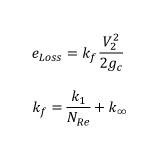
The energy loss is represented by the friction loss occurs during transferring by using the below equation. The kf is the excess head loss from pipe, fitting, and other which are dimension less and can be determined by 2K methods.
In the turbulence flow (high Reynold number), the first term can be negligible, and kf of liquid entering the hole is 0.5 and exits the hole is 1.
Since the storage tank is atmospheric pressure, then the first term, differential pressure and initial velocity (V1) can be eliminated, then from the below equation, the exit velocity (V2) can be calculated by the reducing of the liquid level in storage tank.
The 2-K method presented above is a much more general approach. However, the alternative method which is also applicable to flow through an orifice plate can also be applied. This method will apply the discharge coefficient (Cd) which is equal to 0.61 for a sharp-edge orifice for the Reynolds number greater 30,000.
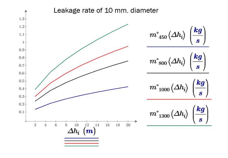
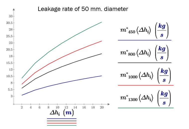
Below are the leakage rates from 10, 25, 50, and 100 mm diameters from the ATM storage tank which contains the hydrocarbon liquid density are 450, 800, 1000, and 1300 kg/m3 respectively.
Understanding the potential explosion pressure allows for the implementation of appropriate safety measures to protection personnel, equipment, and facilities. This may include designing blast-resistant structures, implementing evacuation plans, and providing personal protective equipment.
Blast effects on structure and equipment
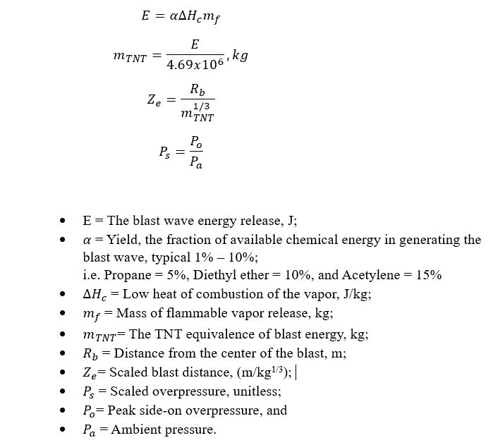
TNT Equivalency
TNT equivalency is a simple method for equating a known energy of a combustion fuel to an equivalent mass of TNT and uses an overpressure curve to apply a point source detonation of TNT.
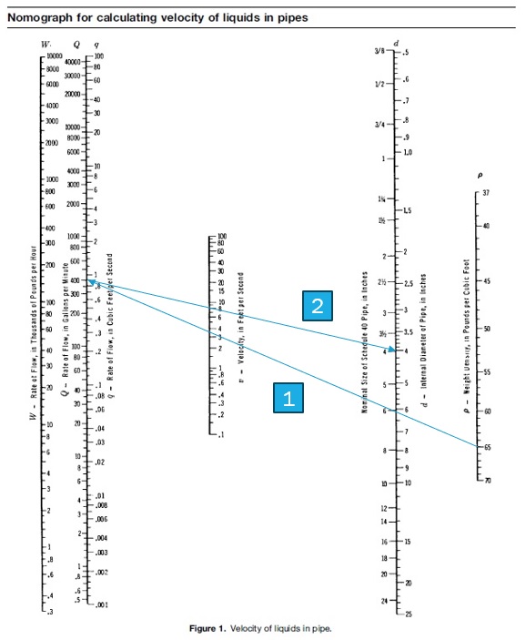
The estimating liquid velocity in the piping offers several benefits such as optimized system performance, prevention of erosion & corrosion, and avoidance of cavitation.
In safety point of view, fluid velocity is one of critical parameters to determine the erosion and corrosive effects on the pipe material. Excessive fluid velocity can lead to the cavitation and can cause damage to the pump when apply the pump series connection or boosting concept.
Erosion Velocity
Erosion velocity refers to the fluid velocity at which erosion of the pipe material begins to occur. One common used empirical correlation is API RP 14E equation, which provides guidelines for estimating erosion velocity in hydrocarbon service.
Example
Estimate the fluid velocity in the 4-inch pipe for carrying the fluid flowrate 400 gallons/min and liquid density is 65 lb/ft3.
From the above figure shown, the result velocity is 8 ft/s which is lower than the erosion velocity at 12.4 ft/s. [100/(65^0.5)]
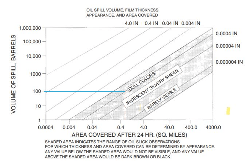
Estimating the potential size and impact of an oil spill is crucial for several reasons such as Emergency Response Planning, Risk Assessment, Environment Protection, Public Safety & Health, and Resource Allocation.
A rough estimate of spill volume can be generated from observation of the oil slick’s size and thickness (1st figure) and the appearance, and light condition (2nd figure).
Example
Estimate the area impact of oil 100-gallon leakage from the offshore platform to the sea surface and spreading with dull colors.
Since the oil slick thickness is unknown, the area covered after 24 hours is between 0.0004 to 0.8 sq. miles. The more conservative area that needs to be investigated shall be as big as possible.
From the table, interpolate 2,500,000 + (100-61.7)*2,500,000/(123.4-61.7) = 4,051,863 sq. ft. or 0.145 sq. miles.
Blast explosions are typically associated with flammable cloud when it is formed during the leakage of flammable gases. If its direct ignition once released lead to a flash fire. If, however, its ignition is for some delayed (5-10 mins), then a Vapor Cloud Explosion (VCE) is the probable outcome.
The study of blast explosions involves understanding the dynamics, effects, and mitigations of these explosions.
Key aspects of blast explosion studies include:
Shockwave Propagation: Blast explosions generate shockwaves the travel through the air, causing damage to structures and injuring people. Understanding how these shockwaves propagate is crucial for assessing the potential impact of an explosion.
Blast Effects: The study can demonstrate the effects of blast waves on structures, infrastructure, and the human body. This includes the evaluation of overpressure (peak pressure), impulse (the total pressure applied over time), and the duration of the blast.
Structural Response: Buildings and other structures react differently to blast loads depending on their design and construction. The design aims to develop methods to design structures that can better withstand blast impacts.
Human Injury and Protection: Blast explosions can cause injuries to humans, including primary injuries from the blast wave, secondary injuries from flying debris, and tertiary injuries from being thrown or crushed. Studies focus on protective measures and strategies to minimize these injuries.
Two (2) main important parameters output from Blast Explosion Study
Peak Pressure (Overpressure): The peak pressure, also known as overpressure, refers, to the maximum pressure level reached by the blast wave during its propagation. It is usually measured in (psi) or (Pa). Peak pressure is a critical factor in assessing the potential damage caused by a blast. Higher peak pressures are associated with greater destructive potential.
Impulse: Impulse is the cumulative effect of the blast wave over time. It is the integral of the pressure-time curve and represents the total momentum imparted by the blast wave. Impluse is calculated by integrating the pressure-time curve over a specified time interval and is expressed in (psi.s) or (N.s/m2)
Damage estimated based on overpressure published by V.J Clancey “Diagnostic Features of Explosion Damage” are given in below table.
psig
kPa
Damage
0.3
2.07
“Safe distance” probability 0.95 of no serious damage below this value. Projectile limit. Some damages to house ceiling. 10% window glass broken.
2
13.8
Partial collapse of walls and roofs of house
3
20.7
Heavy machines (3,000 lbs) in industrial buildings suffer little damage. Stell frame building distort and pull away from foundation.
Parameters Significantly Affecting the Behavior of Explosions
Ambient temperature
Ambient pressure
Composition of explosive material
Physical properties of explosive material (material reactivity)
Nature of ignition source i.e. type, energy, and duration
Geometry of surrounding i.e. confined or unconfined space
Degree of confinement
Amount of combustible material
Turbulence of combustible material
Time before ignition
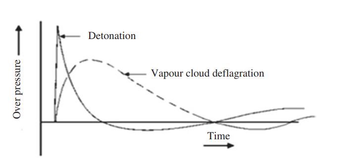
Deflagration and Detonation
The damage effects from explosion depend highly on whether the explosion results from a detonation or a deflagration. Deflagration and detonation are both processes of rapid combustion, but they differ in terms of the speed of the combustion wave and the mechanisms involved. The below table is a summarize of the difference between deflagration and detonation.
Deflagration
Detonation
Speed
Subsonic combustion process
Supersonic combustion process
Propagation
Combustion wave moves through the substance relatively slowly.
Combustion wave moves through the substance very rapidly.
Shock Wave
No strong shock wave produced.
Shock wave is the formation of Detonation.
Example
Burning of a piece of paper.
Explosion of dynamite.
In the detonation mode, the flame front travels as a shock wave and exceeds the velocity of sound (330 m/s) typically of the order of 2,000 – 3,000 m/s. A detonation generates greater pressure than a deflagration explosion flame.
A deflagration can also evolve into a detonation. This is called a deflagration to detonation transition (DDT). The transition is particularly in pipes but unlikely in vessels or open spaces since in the piping system the energy from a deflagration can convert to pressure wave, resulting in an increase in the adiabatic pressure rise.
Key parameters
Ignition of the flammable gas, dust or mist cloud will result in the propagation of a frame front, or deflagration wave. The effect of a deflagration is to increase the pressure-volume product due to a large rise in temperature and a change in mole amount of gas present. Hence, based on this explanation, the relationship of ideal gas equation of state can be applicable.
For the explosion to take place, three conditions must be presented.
Sufficient quantities of flammable fuel, air, and ignition source or cloud dimension;
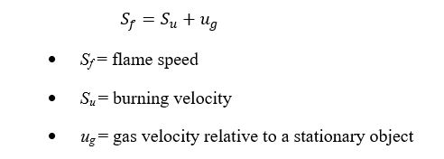
Flame speed (Sf); and
System geometry.
Cloud dimension, R (m), is derive from the volume, V (m3) of the vapor cloud, which is composed from flammable gas and air on the surface. This can be calculated from the reaction’s stoichiometry. The geometry of the cloud dimension could be considered as a hemisphere, as
Burning velocity is defined as the speed at which the flame front propagates through the flammable mixture relative to the unburned mixture ahead of the flame. However, burning velocity does not take into account the flame expansion relative to stationary objects. Hence, when such expansion is taken into account, the term flame speed is used.
As a minimum of flame speed,
However, flame speed (Sf)can become high, particularly in the tube situation where displacement of the gas ahead of the flame creates pipe flow turbulence. Flame speed without turbulence for hydrogen without stationary objects would be about 24 m/s (laminar) but turbulence could lead to flame speed of 240 m/s or more. Hence, the system geometry is more contribute to the pressure of explosion than the flame speed significantly.
The value of the estimate the burning velocity (Su) for a number of gases in air can be referred to NFPA 68.
System geometry
Open area
If the explosion occurs in the unconfined space, it can be called as unconfined vapor or dust cloud deflagration which can presents the hazards of an expanding fireball rather than the detonation since it does not produce large localized overpressure.
The size of fireball generated can be estimated by assuming that a fixed amount of fuel burns with a stoichiometric equivalent amount of air to yield a burned volume at the flame temperature. The increase in volume in volume of the burned mass is estimated by using the relationship of ideal gas equation of state.
For example, the maximum theoretical hydrocarbon’s pressure, with initial pressure and temperature between 1 and 40 bar and 0-300oC.
Shepherd et al. (1997) developed a relatively simple and sufficient accurate model on the basis of energy conservation law applied to a constant volume adiabatic system.
Partially confined
A partially confined deflagration is represented by combustion of a vapor or dust cloud in a small volume of a larger enclosure which the total pressure rise is proportional to the volume of gas burned. The example case are;
Explosion inside the building;
Explosion in vessels and pipes
In case of building with some opening, A simple method to determine the peak pressure has been described by Weibull (1968) as follows.
Unconfined Vapor Cloud Explosion (UVCE) Methods
UVCEs are among the most serious scenarios in QRA consequence assessments, due to the potential huge and large impact on people and assets. The main model and summary of each model are presented as below.
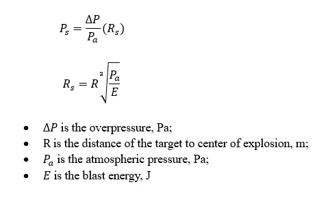
Equivalent TNT Mass Method
Compare heat of combustion with the energy release of TNT which is equivalent to 4.69×10⁶ J/kg
Multi-Energy Model(MEM)
Blast pressure is determined by charts which is defined by scaled pressure and scaled duration against a scaled distance;
Baker Strehlow Tang(BST)
BST methodology requires selection of the maximum flame speed, on the basis of the combined effects of congestion, fuel reactivity, and confinement.
Congestion levels for BST is segregated by area blockage ratio per plane, number of obstacle layers, and pitch.
Reactivity of fuels are defined by burning velocity (Su);
Then, the flame speed correlations are determined by congestion and reactivity.
Blast pressure is defined by above factor including the applying of the chart scaled pressure and scaled duration against a scaled distance same as MEM method.
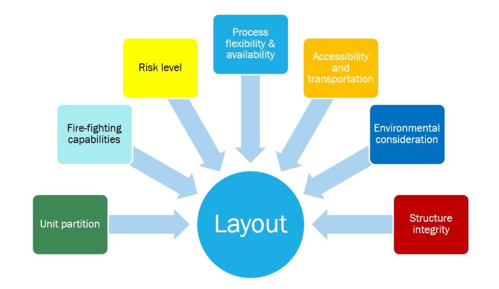
The design of offshore facility layout involves several key elements to ensure unit partition, fire-fighting capabilities, risk level, process flexibility & availability, accessibility& transportation, environmental consideration, and structure integrity. However, at the very end point of the safety, the installation should minimize the potential of gas release or smoke drifting toward the accommodation and primary evacuation point.
If the ingress of smoke or gas is possible, the design of any ventilation system shall take into account since the amount of ventilation available and degree of congestion are significantly influence the severity of an explosion.
To reduce the potential of hazards, the goal is to achieve segregation of fuel ignition sources by separating groups of equipment and defining the compatibility of units between each other. Examples of the separation are the following which are defined from (Fuel Source VS Ignition Source).
Wellhead (FS)
Unfired process (FS): Manifold, header, separator, exchanger, pump, compressor, slug catcher, metering, etc.
Hydrocarbon Storage (FS): Produced water tank, sump tanks, etc.
Fired process (IS): Fired heater.
Machinery and power generation (IS): Generator, Air Compressor, Engine, etc.
Working area and utility equipment unit (IS)
Pipeline and riser (FS): Riser, Pig launcher, pig traps
Vent and Flare (FS & IS)
Transportation (IS)
If the units that are located beside each other are compatible (FS + FS) or (IS + IS), they can be located in the same fire zone. If the case is (FS + IS), a detailed study shall be performed such as locating those two different fire zones, considering the safety distance, performing the quantitative risk assessment, etc.
Working Area
Central Control Room (CCR): This room is a central hub or nerve center located on the offshore platform, where operators monitor and control various aspects of the facility’s operation.
Switchgear room: This room contains all electrical switchboards to distribute generated power to users.
Battery room: This room contains battery racks for the Uninterrupted Power Supply (UPS) system. It shall be ventilated to avoid hydrogen concentration.
UPS room: Dedicated switchboard for system fed by UPS are located in this room.
Telecommunication room: This may contain the telecom console, and the video/radio transmission facilities.
Workshop: This room shall be separated for maintenance and repair activities. It should be separated by function such as Mechanical workshop, HVAC workshop, Instrument Workshop, Electrical Workshop, and etc.
Utility Equipments Area
Firewater pump: Based on NFPA, each living quarter (LQ) shall have a dedicated firewater pump with a redundant system and shall be placed at a suitable distance from the (PP) production platform.
Potable water maker: It shall be installed in a small shelter and placed at the highest elevation for the benefit of gravity pressure.
Gray/black water disposal system: Gray (kitchen, shower, etc.) and black water (toilet) shall be designed with gravity flow and end at the sewage treatment system
Equipment lift: This is installed in case the pedestal crane and laydown areas cannot transfer to LQ.
Aviation refueling station/tank: It is only installed at the highest elevation for quick assess to a helicopter which shall be at a remote location.
Vent and Flare area
Flare platform shall be located far away from production platform (PP);
Ensure that the wind is blowing flare gases away from the complex;
Flare should not be located down-wind of sources of flammable gas;
Cold vent are also considered as the source of release and could become ignition source in case of accidental igition.
Transportation Area
Boat landing: Also known as a marine transfer station where boats or vessels can safely dock, load, and unload passengers, cargo, equipment, or supplies. Key features of boat loading include.
Docking area: The docking area is typically equipped with fenders or bumpers to prevent damage to both the boat and the offshore structure docking maneuvers.
Mooring and Berthing Equipment: Boat landing may include mooring bollards, cleats, or padeye to secure boats in place once they are docked. Mooring lines or ropes are used to tie the boat securely to the offshore structure. This activity shall be very careful since during extreme weather conditions the workboat may drift uncontrolled and clash with the platform (PF)
Access Equipment: Boat landing often have gangways, stairs, or ramps to facilitate the safe boarding and disembarkation of passengers between the boat and the offshore platform.
Lighting and Signage: Boat landing may equipped with lighting system to ensure visibility and safety during nighttime or low-light conditions.
Location: The location of boat landing area should be installed at the opposite side of the flare, and consider the risk of vent, exhaust location, wind, sea swell, current direction, and hazardous area, including wire-line operations.
Ship impact and dropped objects: The risers and conductor should be designed and positioned or minimize the likelihood of damage due to ship impact and drop objects.
Air Transfer: Air transfer refers to the transportation of personnel or cargo via helicopters between onshore bases and offshore facilities.
Helipads and landing facilities: Helipads or designated landing area to accommodate helicopter landings and takeoffs shall be equipped with lighting, marking, and safe
Location: The location of the helicopter approach shall consider the risk of flare, vent, exhaust location, wind direction, and hazardous area. The 210o approach shall be free, up to 1 km away, of any obstacle.
Safety Feature: The safety feature that should be installed on the helipad such as;
Safety Net and Barriers: To prevent from personnel and equipment falling off the platform which should be installed in a cantilevered position.
Fire Suppression System: such as foam monitors or fire extinguishers.
Tie-Down point: Tie-down point or anchoring system shall be provided to secure the helicopter in place during adverse weather condition.
Weather Monitoring Equipment: such as windsocks, anemometers, and visibility sensors should be installed near the helipad to provide real time weather data to pilots.
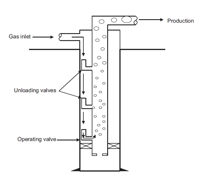
Gas Lift operation is a widely used artificial lift method in the oil and gas industry to increase or maintain the production rate of oil wells.
It involves injecting gas into the wellbore to reduce the hydrostatic pressure of the fluid column (the specific gravity is lowered), thereby allowing the reservoir fluids (oil and associated gas) to flow more easily to the surface. This is because of the injected gas encounters the produced fluid (oil and water) in the wellbore. At a certain depth, known as the bubble point depth, the pressure of the injected gas equals the pressure of reservoir fluid, causing the gas to come out of the solution and form bubbles.
Effect of gas lift to reduce the gas specific gravity in well
The relation of gas injection point and production pressure
Gas Lift system components
The basic equipment for gas lift operation includes the following;
Gas Lift valve (GSV), a pressure regulator device installed on a gas lift mandrel on the tubing string of a gas lift well. There are 4 types of GSV which are 1) casing pressure-operated valve 2) throttling flow valve 3) fluid-operated valve, and 4) combination of fluid-open/pressure-closed valve.;
Wire-line adaptations, a tool to retrieve a dummy valves after finishing the hydrotesting process and use to install the gas lift valves.
Check valves on the gas lift vale, to protects against black flow from the tubing to the annulus;
Gas Lift mandrels, a container in the tubing string that holds a gas lift valve. The conventional type of Gas Lift mandrel is the side-door type, the mandrel system comprised of Gas Lift Valve (GSV), check valve, mandrels itself.
Surface control equipment; and
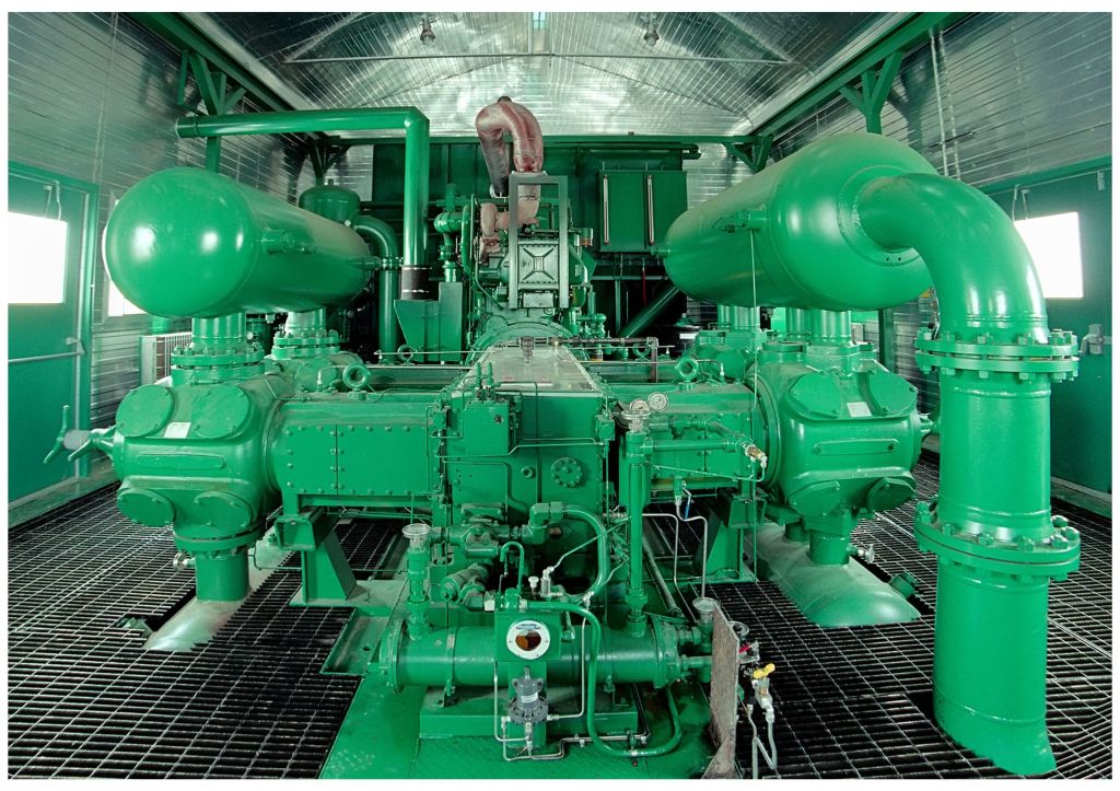
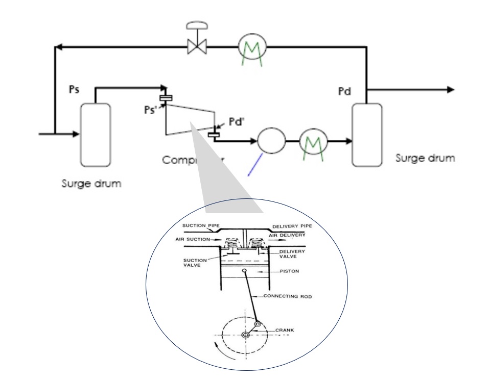
Compressor
The most common failure and cause loss of lifting efficiency
Gas lift system can experience various types of failure or issues that may affect their performance and reliability. Some of most common failure or problem associated with the gas lift operation include:
Gas Compression Issues: Insufficient gas supply or inadequate compression can lead to reduce the gas lift effectiveness since it will reduce gas injection rates and suboptimal lift performance. The example causes are following.
Gas lift wrong design (larger than actually needed);
Hydrate;
Unstable of gas lift supply pressure;
Problem at surface injection flow control valve;
Wrong set point (high/low gas injection flow rate);
High pressure in well head
Problem at gas lift valve (e.g. salt deposition, stuck open due to dirt accumulation)
Gas Leak: Leaks in the gas lift tubing, connections, or surface equipment can lead to loss of gas pressure and reduced injection rates. The example causes are following.
Gas lift valve stuck in open position due to salt deposition or dirt accumulation;
Gas lift valve faulty
Liquid loading: Liquid loading occurs when liquid (e.g. water, condensate) accumulate in the wellbore, obstructing gas flow and reducing life efficiency. Liquid loading can occur due to factors such as declining reservoir pressure, high-gas-to-liquid ratios, or insufficient gas velocity to carry liquids to surface.
Gas Interference: Gas interference occurs when gas bubbles coalesce and form large gas slugs in the tubing, causing flow instability and decreased lift efficiency.
Downhole Tubing Damage: Corrosion, erosion, or mechanical damage to downhole tubing can compromise the integrity of the gas lift system and reduce it effectiveness.