Estimating the leakage flow rate allows the designer to understand the amount of fluid being lost from the system since the leakage of certain fluids, such as hazardous chemicals can pose safety risks to personnel and the surrounding environment. Hence, quantifying the leakage flow rate can help in the mitigation of those hazardous impacts.
For the liquid discharge, the density remains constant during the discharge, then the mechanical energy balance which is derived from the Open System Steady-State Energy Balance can be used to determine the discharge rate model.

The energy loss is represented by the friction loss occurs during transferring by using the below equation. The kf is the excess head loss from pipe, fitting, and other which are dimension less and can be determined by 2K methods.
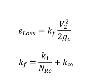
In the turbulence flow (high Reynold number), the first term can be negligible, and kf of liquid entering the hole is 0.5 and exits the hole is 1.

Since the storage tank is atmospheric pressure, then the first term, differential pressure and initial velocity (V1) can be eliminated, then from the below equation, the exit velocity (V2) can be calculated by the reducing of the liquid level in storage tank.
The 2-K method presented above is a much more general approach. However, the alternative method which is also applicable to flow through an orifice plate can also be applied. This method will apply the discharge coefficient (Cd) which is equal to 0.61 for a sharp-edge orifice for the Reynolds number greater 30,000.

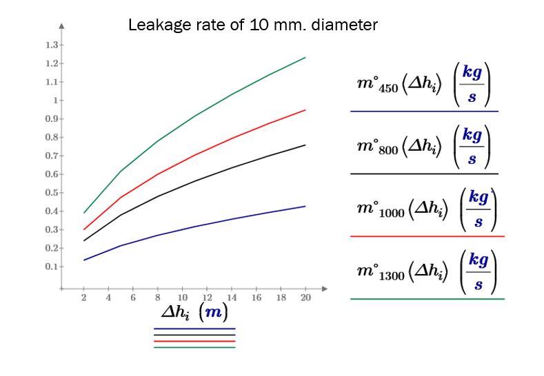
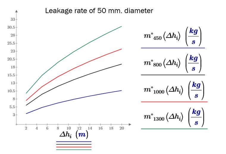
Below are the leakage rates from 10, 25, 50, and 100 mm diameters from the ATM storage tank which contains the hydrocarbon liquid density are 450, 800, 1000, and 1300 kg/m3 respectively.