Appendix B.10, Field devices of ISA-S84.01, Application of Safety Instrumented Systems for the Process Industries has presented the list of potential failures in the sensors system for reference such as;
- Primary sensing elements are prone to failure due to the extreme process conditions;
- Process connection faults;
- Accidentally isolation of the process connection;
- Fluid properties go worst such as Fouling, Corrosion, High viscosity, Clogging, and Pulsation;
- Wiring errors;
- Environmental-mechanic issues such as overheating, freezing, and high vibration.
- Environmental-electric issues such as earthing and bonding damages.
- Adverse weather conditions such as lightning, and flooding.
- Environmental-radiated rays such as RFI/EMI, and X-ray.
The typical failure causes the deficient functionality of the components of the final element (valve) as follows.
- Damages output switch from the logic solver;
- Damages the solenoid valve used to feed and vent the power air or hydraulics;
- Broken of the feed and vent tubing to the actuator
- Malfunction of the actuator itself
- The stuck position of valve steam and seat
Design for fail-safe operation
Fail-Safe Design: A fail-safe system is designed to revert to a predetermined safe state when a failure occurs. This means the designer should design sensors and final elements to result in fail-safe responses to their most likely failure modes.
However, the review of spurious trip rates to see whether they are acceptable shall be performed. A general practice of the fail-safe design of the field device is as follows.
- Sensor contact shall be designed to close during normal operation and will open when fails.
- Output contact shall be designed to close and to be energized for normal operation and de-energized-to-trip design. Actually, the standard allows to use of energized-to-trip design, but it is required to achieve a high safe fraction.
- The system shall trip when the electrical wire is damaged.
- The final valve shall move to the trip position (fail-safe) on the air failure.
- If the SIS signal fails, it shall drive the final to the trip position.
- Typically, a signal < 4 mA is used for tripping the final valve when the sensor is failed.
Separation of sensors from BPCS
Separation: The separation of BPCS (Basic Process Control System) and SIS (Safety Instrumented System) allows for more accurate execution of the situation and allocation of risk. The BPCS is designed to handle routine process control, while the SIS addresses specific safety-related risks. The reasons for not sharing the devices between BPCS and SIS are as follows.
- The potential of common cause of failure
- Loss of the opportunity to have multi number of layers of protection
- Higher failure frequency
- Risk to create confusion for normal routine maintenance and testing for maintaining the safety integrity.
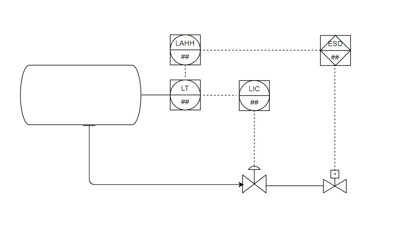
The above illustrates the concept of sharing the level transmitter to control and prevent the gas blow-by due to loss of liquid level in the upstream pressure vessel.
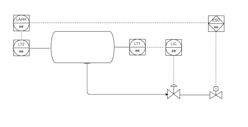
The above illustrates the concept of the separation of the level transmitter to control (LT1) and isolate the SDV valve (LT2) that can prevent the gas blow-by due to loss of liquid level in the upstream pressure vessel.
Diagnostics
Diagnostic functions refer to the capabilities of a system to monitor and assess its own health and performance. It can be considered a self-testing technique. Diagnostic features are designed to detect faults, failures, or deviations from expected behavior within the system. Hence, a high level of diagnostic coverage will convert many potentially dangerous failure conditions into a safe condition with an alarm or safe shutdown.
Proof testing cannot be claimed as a diagnostic due to the frequency of proof testing is very low compared to the potential demand.
Sensor diagnostics:
An example of sensor measurements such as pressure transmitters, level transmitters and etc. Here are some common diagnostic techniques for sensors.
- Self-Test Capability: Modern sensors are equipped with built-in self-test capabilities.
- Redundancy: Redundancy enables fault detection by comparing the outputs of multiple sensors. If one sensor provides a significantly different reading from the others, it will indicate a fault.
- Signal Quality Monitoring: An example of some situations such as sudden spikes, noise, or erratic behavior in the signal will indicate sensor malfunction.
- Comparative Monitoring: Deviation from the expected values can be indicative of sensor drift, degradation, or failure.
Final Element diagnostics:
An example of the final element is the shut-off valve which is required for online testing but it cannot be tested or closed during plant normal operation. Diagnostics provide a prove that the valve is still working properly. Below are the diagnostic test methods for the final element.
- On-line trip testing: Actually, this method is a proof test, not a diagnostic test but to perform this technique, the valve must be equipped with the provision of bypasses.
- Position Feedback Monitoring: The logic solver generates an alarm if the valve position does not match the command.
- Stroke Time Monitoring: Deviation in stork time can indicate issues such as sticking or binding in the final element.
- Partial Stork Testing (PST): PST intentionally tests a portion of the stroke of the final element without putting the entire system at risk.
- Leakage Detection: This technique requires to use of additional measurement for monitoring for any leakage past the final element.
Redundancy in sensors and final elements
Redundancy helps in mitigating the impact of component failures. If service one component fails, the redundant component(s) can take over, maintaining the functionality of the system. The system can continue to operate even in the presence of failures.
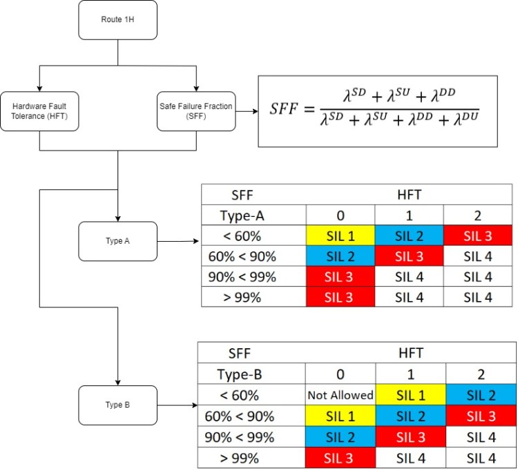
IEC 61508 part 2 places an upper limit of the SIL that can be claimed which depends on the following factors.
- Hardware Fault Tolerance (HFT);
- Safe Failure Fraction (SFF)
Diversity
Diversity means using different types of sensor measurements or different final elements to achieve the same result. The objective is to minimize the possibilities of common cause failure or systematic errors.
